Communications Systems in Battery Chargers
Part of Chapter Charger Alarms and Other Options
Video
INTRODUCTION TO COMMUNICATIONS
6.5.1
In the “old days,” chargers reported alarm status through relays. The relay contacts were used to trigger alarm buzzers, turn fans and indicator lamps on and off, or report status to the main annunciator panel. If analog data, such as voltage or current needed to be reported, transducers were installed in the charger to convert the desired parameter into a 4-20 milliampere or 0-10 volt signal. The transducer signals would be connected to transducer meters for remote monitoring or to Remote Terminal Units (RTUs) for data aggregation. Every alarm and transducer output required a dedicated pair of wires.
SERIAL COMMUNICATIONS BASICS
6.5.2
Serial Communications permit data to be transferred between devices with a minimal number of wires (typically three). The data is transferred via a sequential series of pulses and the amount of data transferred, or bandwidth, is only limited by the size of the pulses. These pulses can be created by varying the voltage on one end of a copper wire, or by turning on and off a light source on one end of an optical fiber.
The data to be transferred is converted to a binary bit stream. The rules for “serializing”, or breaking the data into a stream of pulses, must be defined at each end of the communications channel such that the receiving end can restore the original data from the series of pulses it received.
SYNCHRONOUS VERSUS ASYNCHRONOUS
6.5.3
Devices on both sides of the communications channel need to be synchronized such that the receiving device will detect when and how to reconstruct the bit stream. Time synchronization can be accomplished two different ways, with synchronous or asynchronous data formats.
Synchronous Formats
6.5.3.1
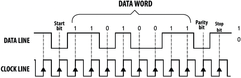
Synchronous formats (see Figure 6b) require an additional CLOCK line signal connected between the devices. The signal on the DATA line will change on every rising or falling edge of the CLOCK line. The data line is sampled at the receiving device on the opposite clock edge (middle of pulse). Neither device needs to be configured for the data rate, and the data rate may change dynamically.
Asynchronous Formats
6.5.3.2
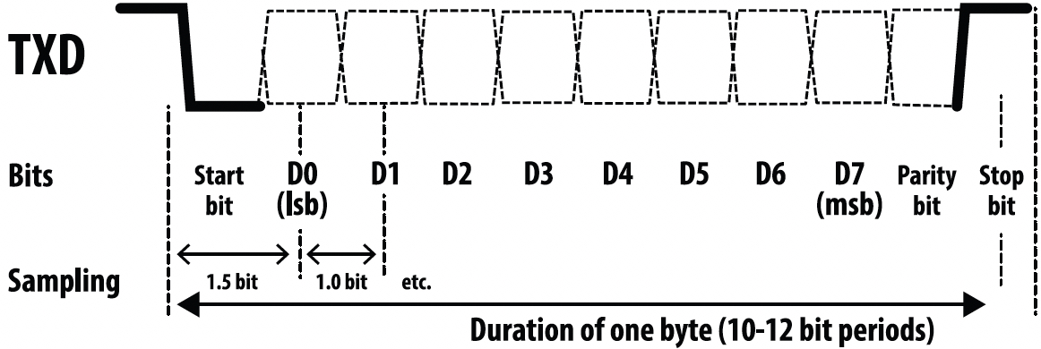
Asynchronous formats (see Figure 6c) do not require a CLOCK line; only a DATA line is connected between the devices. The receiving device monitors the DATA line and will synchronize or FRAME the bit stream based on a transition event. Most asynchronous formats use a falling edge after a period of inactivity as the synchronization method. The DATA remains low for one bit time and this is referred to as a START BIT.
Devices that communicate asynchronously must be configured to use the same bit time-period (or BAUD rate). Receiving devices detect the start bit’s falling edge and sample all remaining bits of the stream in the middle of bit time. Asynchronous formats are preferred because they require fewer connections. Fewer connections also reduce the amount of wire (or fiber), terminals, connectors and thereby cost.
SERIAL CONFIGURATION PARAMETERS
6.5.4
Framing
6.5.4.1
Asynchronous communication information-packets are sent in frames. At a minimum, a frame consists of a START BIT, the payload (actual data bits D0-D7), and a STOP BIT. A frame may include additional error checking bits (PARITY) and/or stop bits. Devices that communicate asynchronously must be configured to follow the same set of rules. Most devices will allow these parameters to be configured to ensure operability with other serial devices.
BAUD Rate
6.5.4.1
Since there is no CLOCK line between the devices, each device must send and receive data using the same bit time. This bit time is referred to as the BAUD rate. There are several standard BAUD rates for serial communication ports ranging from 110 bits per second up to 256,000 bits per second. The typical rates supported by most devices range from 9600 to 115,200 bits per second.
Number of Data Bits
6.5.4.3
The DATA BITS (D0 thru D7) are the payload of the frame. Most modern protocols transfer data in bytes (eight bits at a time). Some data protocols transfer data in ASCII which utilizes a seven-bit format. An older version of the Modbus protocol (described in SECTION 6.5.9) utilizes the ASCII data format.
Parity
6.5.4.4
An extra error detection bit may be added to each frame. This bit can be configured to transfer an EVEN PARITY BIT or an ODD PARITY BIT. If EVEN PARITY is selected, the PARITY BIT will be set to ‘1’ when there is an odd number of ‘1’s in the data bit fields (D0-D7). If ODD PARITY is selected, the PARITY BIT will be set to ‘1” when there is an even number of ‘1’s in the data bit fields (D0-D7).
Stop Bit(s)
6.5.4.5
All frames must end with one (or two) STOP BIT(s). A STOP BIT is a high or logic ‘1’ bit at the end of the frame. The STOP bit returns the bus to the idle state, which is the logic ‘1’ state.
COMMUNICATIONS ERRORS
6.5.5
Devices with matching configuration and correct cabling will communicate without errors. The following error messages are standard for most devices with serial communications. Error messages can be helpful in determining a mismatched configuration or an application issue.
Framing Error
6.5.5.1
A framing error occurs when a device detects a START BIT, but not the STOP bit(s). It may indicate a configuration mismatch between devices for: BAUD rate, parity, number of data, or number of stop bits. This error may also indicate an unreliable connection due to excessive cable length, improper terminations, poor shielding or excessive electrical noise.
Parity Error
6.5.5.2
If parity checking is enabled, all devices receiving data will check the parity bit on every frame. Frames received with incorrect parity will generate a parity error. Most devices ignore messages received with a parity error. This error may indicate a parity configuration mismatch or an unreliable connection due to excessive cable length, improper terminations, poor shielding or excessive electrical noise.
Overrun Error
6.5.5.3
An overrun error is rare and typically only occurs if the device cannot process messages and frames fast enough such that a new frame is received before the device can process the previous frame. If this error occurs, reduce the device’s BAUD rate and polling rate.
CONNECTING TO THE NETWORK
6.5.6
Most chargers support RS-232 and RS-485 networks with master/slave protocols. Ethernet connections with multiple protocol support are now becoming more common. Fiber optic versions of both serial and Ethernet networks are often implemented to provide isolation between network devices.
RS-232
6.5.6.1
The RS-232 standard was used by personal computer (PC) serial ports prior to the development of the USB standard. RS-232 provided a simple connection from the PC to mice, printers, and/or modems. The standard was designed to connect two devices together that are a short distance apart. This standard has limited cable length (typically less than 50 feet) and is susceptible to electrical noise.
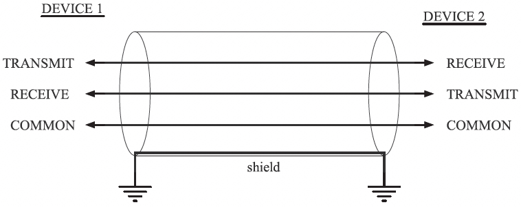
The simplest RS-232 connection (see Figure 6d) consists of three wires, a TRANSMIT, a RECEIVE, and COMMON (or GROUND). The TRANSMIT of one device is connected to the RECEIVE of the other device. The COMMON of both devices are connected to each other.
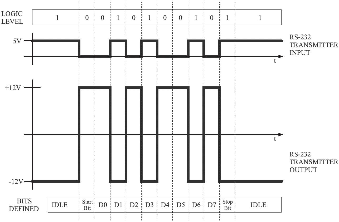
RS-232 signals are inverted at both transmitter and receiver. As seen in Figure 6e, a logic “high” signal at the transmitter’s input is translated to a logic “low” at the output of the transmitter. A logic “low” signal input to a receiver is translated back to a logic “high” at the output of the receiver.
The signal level for RS-232 is typically (+/- ) 12 volts such that a high level or mark condition on the driver’s input will result in – 12 volts on the driver’s output. A low level or break condition on the driver’s input will result in +12 volts on the driver’s output.
Most newer RS-232 receivers will support signal levels down to (+/-) 3 volts to ensure compatibility with lower voltage RS-232 drivers. The transition between logic levels on RS-232 receivers is zero volts regardless of the threshold voltage.
Some older implementations of RS-232 supported hand shaking signals RTS (Ready-To-Send) and CTS (Clear-To-Send). This interface used five wires instead of three. The additional two wires were used to connect the RTS of one device to the CTS of the other device. The hand shaking signals were used to throttle the communications between older, slower devices to make sure the devices were ready to accept more data before the data was sent.
RS-485
6.5.6.2
The RS-485 standard defines electrical characteristics of drivers and receivers for use in balanced digital multipoint systems. RS-485 allows multiple devices to be connected to the same network (up to 32 standard devices). Balanced networks are much less sensitive to electrical noise and will support distances of 1000 meters.
RS-485 networks have TRANSMIT and RECEIVE differential connections and a COMMON (or GND). RS-485 drivers convert a single-ended TTL signal to a differential signal pair; RS-485 receivers convert a differential signal pair back to a single-ended TTL level signal. Most protocols that support RS-485 are master/slave. One master device will poll all other slave devices on the RS-485 network. Slave devices will only respond when polled.
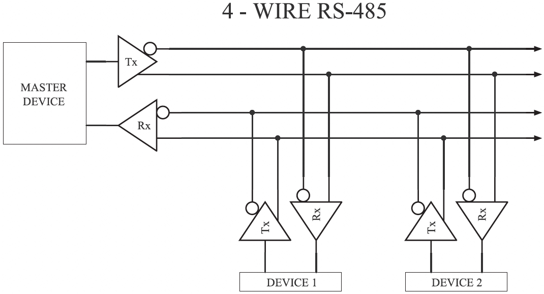
In a 4-wire RS-485 network (see example in Figure 6f), the master TRANSMIT pair is parallel wired to all slave devices’ RECEIVE pairs. All slave TRANSMIT pairs are parallel wired to the master’s RECEIVE pair. The COMMON of each device is parallel wired together – though this is not pictured in the diagram below. The network typically consists of two twisted-pair cables and a common or shield connection.
The sequence of operation of a 4-wire RS-485 network is as follows:
- The master sends a poll message directed to a specified slave device.
- All slave devices receive the poll request.
- The specified slave device will turn on its transmitter and respond to the poll request.
- The slave address turns off its transmitter after the message is sent.
- The master sends out the next poll message and the process continues.
Since there is a separate TRANSMIT pair and RECEIVE pair with 4-wire RS-485 networks, full duplex communication may be supported. Full duplex communication allows the master device to poll the next slave device, while it is receiving the response from the previous slave device’s poll. If full duplex communication is supported by all devices on the network, the master device could issue the next poll during step 3 in the sequence listed above.
Full duplex operation does improve the communication bandwidth of the network since two devices can be transmitting at the same time, but not all devices support full duplex operation. Half duplex is by far the more common RS-485 configuration. In half duplex mode only one device can transmit at a time. Since only one device is transmitting at a time, only one twisted pair connection is required. All devices, both master and slave, can transmit and receive messages over the same twisted pair. This connection method is referred to as a 2-wire RS-485 network.
In a 2-wire RS-485 network (Figure 6g), the TRANSMIT and RECEIVE differential signals of each device are parallel wired to the same twisted pair. The COMMON of each device (not shown) is also parallel wired together. The network between the devices typically consists of a twisted-pair cable with a common or shield connection.
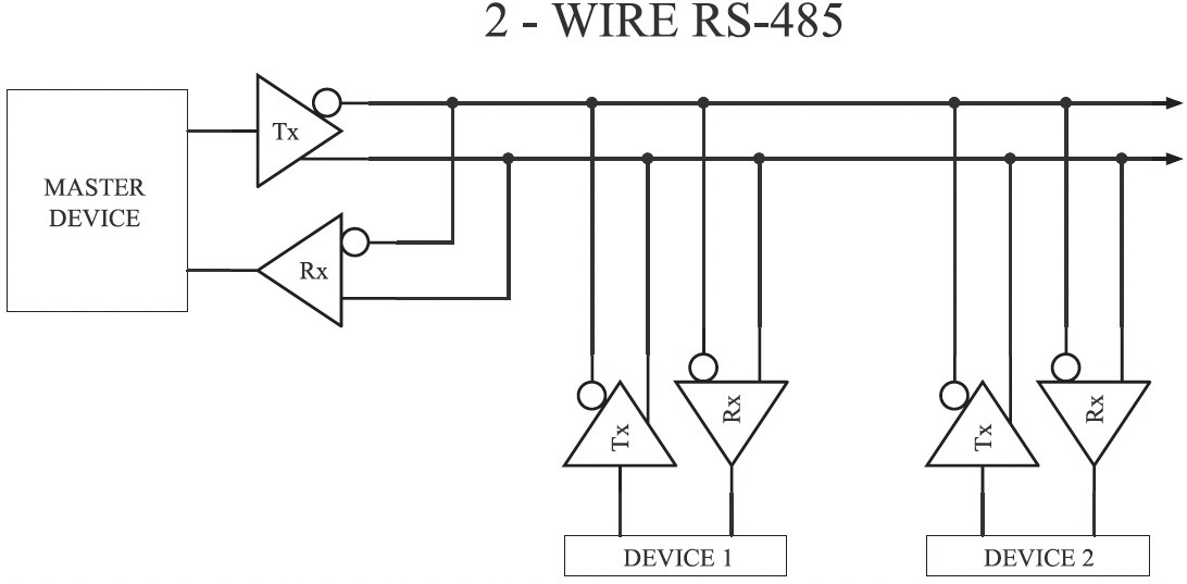
The sequence of operation of a 2-wire RS-485 network is as follows:
- In the idle state, all devices have their transmitter turned off.
- The master device initiates a poll by turning on its transmitter.
- The master sends the poll message and turns off its transmitter.
- All slave devices receive the poll request, but only the slave device that the message was directed to will respond.
-
The specified slave device will turn on its transmitter and respond to the poll request.The slave device turns off its transmitter after the message is sent.The network is back in the idle state and the master device initiates the next poll.
RS-485 Differential Signals
6.5.6.3
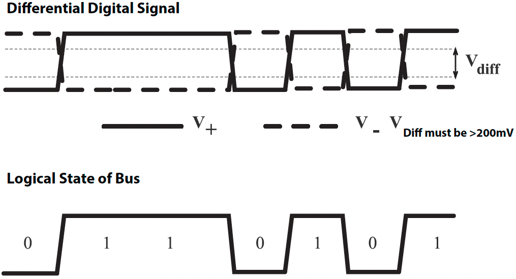
The differential signal pair consist of a (V+) and a (V-). The logical state of the bus is determined by the voltage difference between (V+) and V(-) as pictured in Figure 6h. These signals are referenced to each other, not to ground.
A high logic state is present when there is a positive voltage differential at (V+) when referenced to (V-).
A low logic state is present when there is a negative voltage differential at (V+) when referenced to (V-). A 200mV differential voltage is required to ensure a valid state.
RS-485 Biasing Resistors & Termination Resistors
6.5.6.4
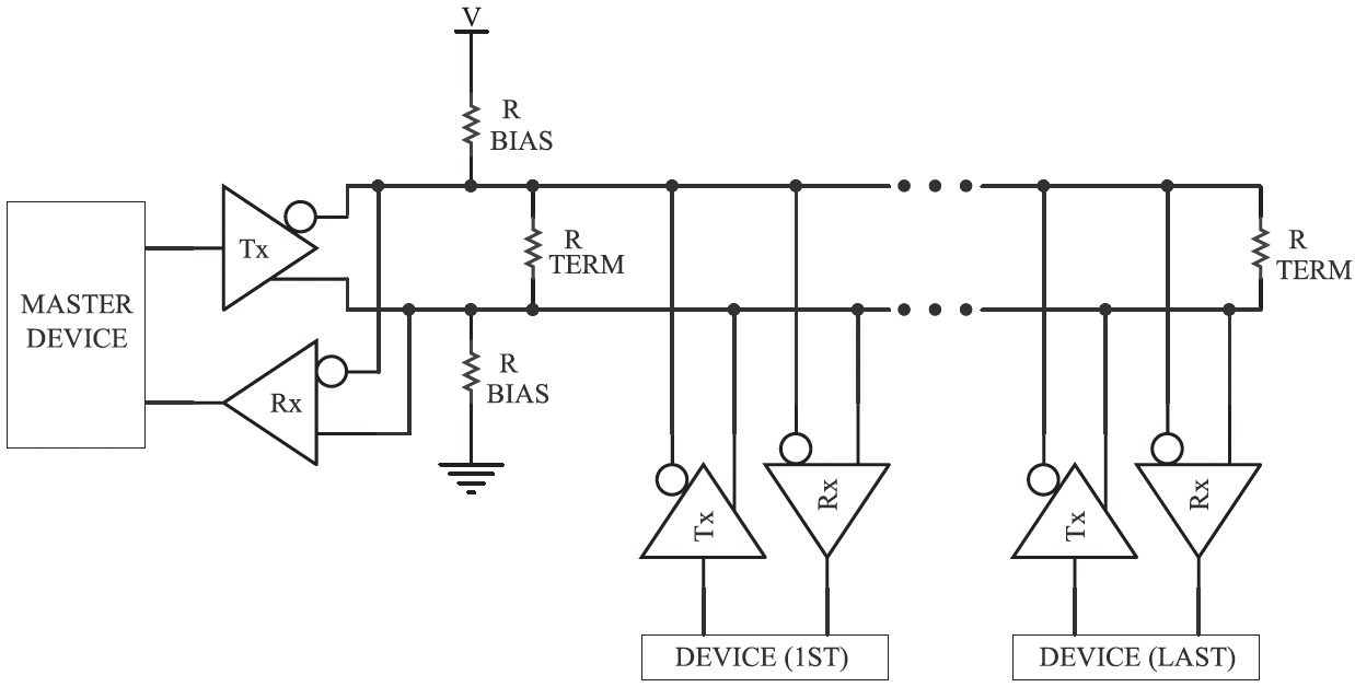
Long RS-485 networks with high BAUD rates may require 120 ohm terminating resistors at both ends of the network as seen in Figure 6i. Termination resistors reduce reflections which appear as ringing at the signal transitions points. The decision of whether to use termination resistors should be based on the cable length and the BAUD rate of the transmission. In most cases, BAUD rates under 19.2 K do not require termination resistors. If termination resistors are used, the network must be designed with the appropriate biasing resistors to ensure reliable communications.
Biasing resistors are responsible to ensure that a network remains in the idle state when all the network drivers are tri-stated (all transmitters turned ‘off’). A 200mV differential must be present between (V+) and (V-) to keep the bus in an idle state. Most master devices include some high resistance biasing (50-100 kohms). When termination resistors are used, the resistance of the biasing resistors needs to be much lower to maintain the 200mV differential. Termination resistors also increase the dc loading of the network.
Network design, including termination resistor and biasing resistor calculations depend on the type and number of devices on the network, the cable length, and the network BAUD rate. For more information on biasing and termination resistor calculations and recommendations, refer to:
EIA/TIA-485 Standard
RS-422/RS-485 Application Note (© Advantech B+B Smartworx)
Ethernet
6.5.6.5
Ethernet is a family of computer networking technologies commonly used in local area networks (LANs). Several variants of Ethernet are available. Older networks utilized coaxial cable to create the connections. Present networks utilize standard cables of multiple copper twisted-pairs with RJ45 connectors on each end. Speeds of 10, 100, and 1000 megabits per second are supported. An Ethernet network permits many devices to be interconnected and allows the devices to communicate via multiple protocols simultaneously.
Connecting a battery charger to an Ethernet network is as simple as plugging in the RJ45 cable. The connection to the network via hubs, switches, and gateways is no different than the connection for a desktop personal computer. The charger will require some configuration to interface to the network. The IP Address, the Netmask, and Gateway Address are standard configuration parameters utilized by all Ethernet devices. Security, access, and firewall configuration are well beyond the scope of this book.
The network topology is typically defined and specified by the Information Technology (IT) department and the network administrator.
Isolation
6.5.6.6

The charger communications discussed thus far have been wired connections which require the charger to be electrically connected to the network. The network may consist of many devices spread out over thousands of feet, meters, or miles. Without isolation, the charger’s electronics could be damaged by currents and surges on the network. It is smart, therefore, to isolate the communications circuit from the rest of the charger’s electronics.
The isolation barrier should be galvanic such that no current flows between the communications electronics and the rest of the charger. Each side of the isolation barrier will have a separate ground and power supply. There is no direct conduction path across the isolation barrier; the information or data is passed from one side to the other magnetically or optically.
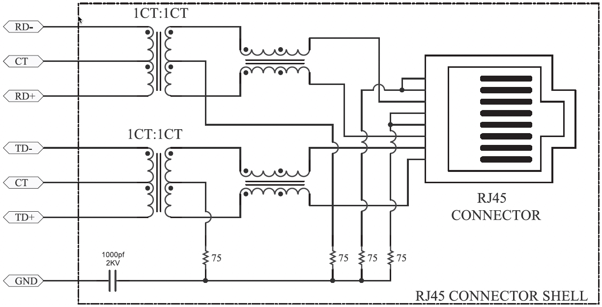
Ethernet driver and receiver circuits use transformers to magnetically isolate the charger electronics from the network cable connection. Many Ethernet RJ45 sockets have the isolation magnetics built into the connector shell, as pictured in Figure 6j.
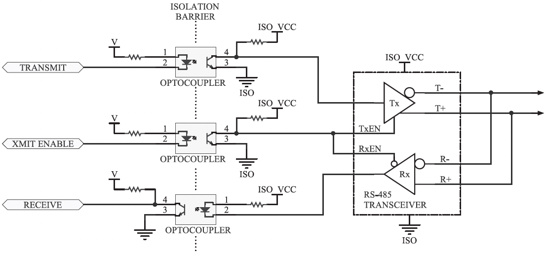
Optical isolation is typically used on RS-232 and RS-485 ports. Optocouplers use light to communicate across the isolation barrier. An optocoupler is a device that has an emitting LED and a detector circuit inside the same semiconductor device. The following example (Figure 6k) shows an RS-485 transceiver isolated from the core circuitry using three optocouplers. Notice each side of the isolation barrier has a different power supply.
Fiber optic networks communicate through either glass or plastic fibers. Each fiber has a light source on one end and a light detector on the other. Depending on the bandwidth and fiber type, cable lengths over a mile can be supported without any repeaters. Since no copper connections are required, all network devices are electrically isolated from each other. When a charger is connected to a fiber optic network, it too is isolated from other network devices; this protects its electronics from network surges.
Fiber modems are available from several manufacturers. These devices convert standard RS-232 and/or RS-485 signals to a serial fiber transceiver. Any RS-232 or RS-485 network connection can be converted to a fiber interface by replacing the copper network with fiber optic cables and inserting one of these fiber modems at each end of the fibers.
Fiber translators or media converters are available for Ethernet applications as well. There are numerous fiber formats. These vary by connector type, fiber type, and wavelengths and BAUD rates supported. Verify the parameters and details of the fiber network before specifying a fiber interface for your charger.
PROTOCOLS
6.5.7
The first sections of this chapter covered electrical standards and configuration options. Once an electrical standard has been selected and the charger is wired to the network, the configuration parameters need to be set correctly. Next, a network connection can be established and the transferring of data can begin.
The protocol specifies how to interpret the data being transferred between the devices on the network. Think of the network connecting the devices like a phone line connecting two people. The protocol between the two devices would represent the language being spoken by the two people. If the two people aren’t speaking the same language, their voices (the data) will get transferred through the phone, but neither person will know how to interpret the data.
Protocols are like languages; they are rules for how data is interpreted between two devices. Languages use words to communicate; protocols use numbers. Protocols in their simplest form outline a few command formats, assign the commands to numbers, and define the rules required to format the data into the commands that have been established.
DATA TYPES, REGISTER MAPS & MINIMAL COMMAND SET
6.5.8
At a minimum, two types of data need to be represented: binary (bits) and analog. A binary is used to specify a parameter such as an alarm that only has two states. The alarm is either ACTIVE or NOT ACTIVE. Examples of the status of other binary data would be ON/OFF, OPEN/CLOSE, ENABLE/DISABLE, or HIGH/LOW. Analog data specifies a parameter with a value such as a measurement. Voltage, current, temperature, and alarm set points are all examples of analog parameters.
The format of the data is specified by the protocol as well. Bytes are the basic building block of serial communications and most protocols size the data types to fit into one or more bytes. Eight binaries (or bits) are packed into one byte. Analogs are one, two or four bytes in length. The format of the data and packing order of the data are all specified by the protocol rules.
Based on the rules of the protocol, a register map will be created by the charger manufacturer. The register map will list the relevant parameters grouped by type. Most protocols will distinguish between analog values that can only be read and analog values that can be read or changed. A measured value such as the dc bus voltage can only be read by an external device. A changeable set point such as an Equalize Timer can be read or changed by an external device. The same is true with binary data types. The status of an alarm can only be read. A control binary, such as FLOAT/EQUALIZE control, can be read to determine the present charge mode status or written to change the charge mode.
MODBUS
6.5.9
The Modbus protocol was created in the late 1970s by Modicon, a Programmable Logic Controller (PLC) manufacturer. The protocol is simple, royalty free and has become a stan-dard for networking electrical industrial equipment. Modbus is a master/slave protocol such that one master device on the network is responsible for polling the remaining slave devices. The slave devices only respond when they are polled by the master. Chargers typically are Modbus slave devices and get polled by Modbus master devices such as Remote Terminal Units (RTU) and Programmable Logic Controllers (PLC).
There are two versions of the protocol: Modbus-ASCII and Modbus-RTU. The ASCII version of Modbus communicates via the seven-bit ASCII code character set. The messages are delineated by special ASCII characters. Modbus-ASCII was designed for older slower equipment that could not meet the timing requirements of the Modbus-RTU version. Modbus-ASCII is a legacy protocol and is rarely used.
Modbus-RTU utilizes eight-bit hexadecimal numbers. Messages are delineated by a 3.5-character timeout before and after each message. This character gap is used to synchronize all devices connected to the network. This character gap requires all frames within the message to have less than a 3.5-character gap or the frames will be interpreted as being in different messages.
The Charger Register Map would include registers for:
- Coils: for readable and writable binaries
- Binary Inputs: for read-only binaries
- Holding Registers: for readable and writable analogs
- Input Registers: for read-only analogs
The suggested minimal command set would include:
- Function Code 1: Read Coils
- Function Code 2: Read Binary Inputs
- Function Code 3: Read Holding Registers
- Function Code 4: Read Input Registers
- Function Code 5: Force (Write to) a Coil
- Function Code 6: Write Holding Register
All Modbus devices must be assigned a Modbus address. Modbus master devices direct commands to slave devices based on the slave’s Modbus address. The format of all Modbus poll-request commands is similar. The commands all start with the Modbus address of the device the poll is directed to and the function code to execute. After the function code, an address field follows to specify which registers are to be operated on. For read commands, these will be the registers’ values returned to the master. For write commands, these will be the registers to be written to, with the data following the register address.
Both the ASCII and RTU version of Modbus include a checksum at the end of each message. The checksums types are calculated differently. Modbus-ASCII uses an LRC; Modbus-RTU uses a CRC. Before a message is processed by a master or slave, a checksum is run on the received bytes of the message. If the checksum doesn’t match the checksum at the end of the message, the message is considered invalid and is not parsed.
For more details about the Modbus protocol visit www.Modbus.org. The specification can be downloaded from the site. The specification will include more information on the data types and commands supported, how to calculate the LRCs and CRCs, exception codes, and much more.
DNP3
6.5.10
DNP stands for Distributed Network Protocol. As described at www.dnp.org, “The development of DNP3 was a comprehensive effort to achieve open, standards-based interoperability between substation outstations and master stations for the electric utility industry. Since its inception*, DNP3 has also become widely utilized in adjacent industries such as water/waste water, transportation and the oil and gas industry.” In fact, DNP3 is based on IEC 60870-5 which was envisioned to become the standard protocol utilized by electrical utilities at the substation level.
The DNP3 protocol is much more complex than Modbus. DNP3 can be implemented as a master/slave protocol for basic applications. The protocol also supports multiple masters and report-by-exception modes such that one master device doesn’t control the network access. In addition, DNP3 has many more data types and variations of data types such as frozen values, changed values (with and without time), and values with and without flags.
There are several subset levels of DNP3 defined to ensure DNP3 operability between simple lower level devices. The lower subset levels only need to parse a few commands and data types. Subset Level I would satisfy most charger communication requirements. The DNP3 protocol refers to data items as points, not registers.
The Charger DNP3 Point map would include points for the following data objects:
- Binary Inputs: for read-only binaries
- Binary Outputs: for readable and writable binaries
- Analog Input: for read-only analogs
- Analog Outputs: for readable and writable analogs
The suggested minimal command set would include:
- Class 0 Read: This would return all points
- Control Relay Output Block: This would implement writes to binaries
- Direct Operate Analog Output Block: This would implement writes to analogs
All DNP3 devices must be assigned a DNP3 address. All DNP3 messages have a header that specifies the source and destination of the message. The simplest way to poll data from a simple DNP3 slave device is to issue a CLASS 0 Read command. The device will respond with all the data points in the point map.
The DNP3 master device will need to issue a Control Relay Output Block (CROB) to change the state of any of the Binary Outputs (control bits). A Direct Operate command must be sent to change the state of any of the Analog Outputs. All DNP3 commands have multiple CRC checksums interspersed throughout each message. If a checksum doesn’t match, the message is considered invalid and is not parsed.
For more details about the DNP3 protocol visit: www.dnp.org.
IEC 61850
6.5.11
IEC 61850 is an international standard defining the communication protocols for devices in electrical substations. This standard was developed by an IEC project group consisting of members from various vendors and countries. The goal of the group was to define abstract data models that can be mapped to several protocols. IEC 61850 devices use Ethernet TCP/IP networks to communicate with each other. Presently the mappings support MMS (Manufacturing Message Specification), GOOSE (Generic Object-Oriented Substation Event) and SMV (Sampled Measurement Values).
As mentioned in the previous section, DNP3 was developed and adopted to simplify equipment interoperability within the substation. Equipment manufacturers standardized on the DNP3 protocol to eliminate the need for the utilities to support multiple protocols and purchase protocol translators. All the substation devices could now speak the same language.
IEC 61850 takes this standardization to the next level; it standardizes the data naming and mapping as well. IEC 61850 is an object-oriented protocol with a standardized naming format. Devices that support DNP3 have tables of points grouped by their data type (binary, analog, input, output, etc.). Each DNP3 device has its own unique data maps and point names. A writable data value such as “High DC Voltage Alarm” is common for all chargers and charger manufacturers. Most chargers will have this same data point, but this data point will have a different name, point number, and location in each manufacturer’s charger.
IEC 61850 eliminates the need for the utility to review the manuals of each device in the substation to determine how to request the specific data values (or data points) they require. IEC 61850 standardizes the names of the data values. The standard names are more readable and intuitive since they contain characters and numbers.
This section was meant to provide a basic understanding of the differences between IEC 61850 and DNP3. The details of the IEC 61850 protocol are well beyond the scope of this text. At the time of printing, Modbus and DNP3 are the most commonly used protocols supported by utility-industry stationary battery chargers. Substation devices that support IEC 61850 are becoming more commonly available. The assumption is eventually the demand for chargers with IEC 61850 support will also grow.
Instructors
Art Salander, Senior Life Member – IEEE
Sr. Applications Engineer / Business Development
HindlePower, Inc.