AC Power Input: What Factors Should I Consider?
Part of Chapter Utility Battery Chargers

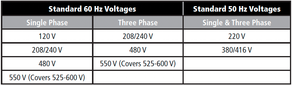
NOW THAT YOU know the charger rating you need, consider how to provide it with ac power. You can order a charger to operate on virtually any of the worldwide standardized ac mains voltages (up to a maximum of 600 Vac), as noted in Table 2a.
HOW MIGHT THE INPUT VOLTAGE SELECTED AFFECT COST?
2.4.1
The standard LVAC (low voltage ac) distribution voltages for the western hemisphere and for Europe are shown in Table 2a in the last section. Usually, utilities maintain a voltage within ±5%, but as you know, brownouts happen. NEMA PE 5 requires a charger to operate with an input voltage 12% below the nominal. This means that a charger wired for 120 Vac input can operate with an input as low as 105 Vac. At the high end, the NEMA standard allows the input voltage to be 10% over nominal.

As you know, the ac input current depends on your choice of input voltage: the higher the voltage, the lower the current. This could have an impact on your wiring costs. Always choose the highest branch ac voltage available at your site that is convenient for wiring.
Single-phase chargers can accept any voltage from 120 V to 480 V or higher. However, 120 Vac isn’t available on some large charger ratings, such as 130 V at 50 Adc; for these ratings, you would select 208 Vac or higher. And of course, 120 V isn’t available on three-phase chargers at all.*
You also may have a choice between single-phase and three-phase ac inputs. In general, a single-phase charger costs less than a three-phase charger, and the site wiring costs may be affected. Here’s a little table (Table 2b) to help you decide, based on the popular 130 Vdc, 50 A charger rating:
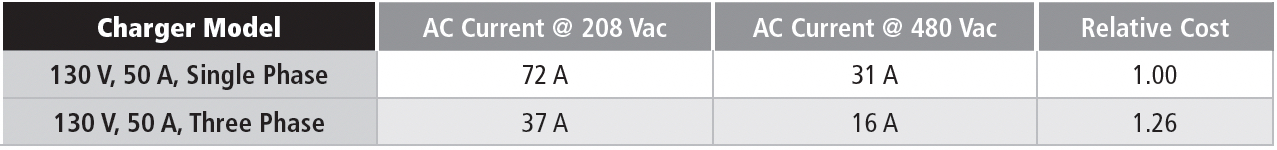
Although you would need larger wire and a larger branch circuit breaker (see boxout ABOUT THAT BREAKER…) for the single-phase charger, you’re running only two wires instead of three, and you have the offset of the lower charger cost. Of course, there may be other considerations, such as maintaining balance on a distribution transformer, that will dictate your use of a three-phase charger. Decisions, decisions...
ABOUT THAT BREAKER...
Circuit breaker ratings can be complex. AC circuit breakers with trip ratings up to 100A use a hydraulic/magnetic trip mechanism. This breaker type is sensitive to the average value of the input current.
AC breakers with trip ratings over 100A use a thermal/magnetic trip mechanism, which is sensitive to the rms value of the input current.
What is the difference? The rms value is a mathematical representation of the effective, or heating, value of an ac current. Normally, the rms value of an ac input current will be a little larger than the average value.
Both circuit breaker types provide safe and adequate protection for the charger and the ac power source it’s connected to.
An important specification for circuit breakers is the ampere interrupting rating. For more on this, see Standards & Codes in CHAPTER 9.
DETERMINING THE AC INPUT CURRENT
2.4.2
The ac input current is generally published in the charger manufacturer’s literature. The published value is usually the maximum current under all worst-case conditions: extremes of ac input voltage, maximum output current limit, and maximum battery equalize voltage.
Chances are good that you’ll never see an input current that high. First, you probably aren’t equalizing the battery at the maximum available voltage, and the ac input current is usually close to the nominal value. But since the charger’s ac input circuit breaker must be sized for the maximum possible current, your wiring and your branch breaker must do the same.
This brings up a very important point. To meet agency certification requirements, the charger’s input breaker must be rated to carry 25% more than the actual maximum input current (and could be as much as 100% higher). Since circuit breakers are available only in certain increments, you should rate your wiring and branch breaker according to the charger’s input breaker rating, not the published input current rating.
Another important rule: You must size your branch circuit wiring according to the trip rating of your branch circuit breaker, not the input breaker in the battery charger. Your branch circuit breaker will be rated the same as, or larger, than the charger’s input breaker.
There are some infrequent applications where you might order a charger with multiple input voltage capability, such as 120/240 Vac. The charger’s input breaker trip rating has to carry the input current for 120 Vac, but you might actually wire the charger for a 240 Vac input. In cases like this, the ac input breaker might be rated for even more than 200% of the actual input current.
AC INRUSH CURRENT
2.4.3
Most available stationary chargers are based on circuits using line frequency transformers. Like ac motors, transformers have an inrush current when ac voltage is first applied, due to the initial magnetizing current requirement. The inrush current is large but lasts only for one or two cycles of the line frequency.
Maximum inrush is specified as a peak current, expressed as a multiple of the normal full-load ac current. If the full-load input current is 16 Aac (from Table 2b, SECTION 2.4.1), and the inrush is 15 times, then the peak inrush current is 15 × 16 × √2, or about 340 amperes. The branch circuit breaker must be rated to withstand this inrush for at least two cycles; we recommend a medium or long time-delay circuit breaker. If your branch circuit breaker has an adjustable magnetic trip, set it to its maximum value. See the boxout on the previous page for additional technical details on circuit breaker ratings.
SOFT START
2.4.4
Soft start (also known as “walk-in”) is unrelated to the ac inrush current. You’re going to have an inrush current whether the charger is equipped with soft start or not.
The soft start feature slowly ramps up the dc output current from zero to its maximum required value, over a period of a few seconds to 10 seconds or more. It was initially added to battery chargers to prevent oscillation or overshoot in the output voltage when an underdamped charger* was connected to a relatively small battery. The requirement now appears in most charger specifications. Soft start also reduces transients fed back to the ac source, in case the charger is operating from a generator, since a generator may have a higher source impedance than a normal ac supply.
INPUT VOLTAGE & CURRENT HARMONICS
2.4.5
The ac voltage delivered by the utility to your battery charger, or any other device or equipment, is a pure sine wave, or at least it’s supposed to be. If you would like more information on ac voltage and sine waves, see Under the Hood: Sources of Ripple in SECTION 3.2.
The current that is drawn by ac-operated equipment, though, might not be a pure sine wave. If the ac load is a pure resistance, such as incandescent lighting, the current will be sinusoidal. This is also true of loads like small ac motors. These are examples of linear loads; in this sense, linear means that the current follows the voltage, and isn’t interrupted during any part of the ac line cycle. A linear load won’t cause any harmonic currents or voltages to be generated; that is, its harmonic distortion is zero.
If there are linear loads, then there must be non-linear loads, right? A non-linear load is characterized by a load current waveform that doesn’t look like the voltage waveform; that is, it’s non-sinusoidal. It causes harmonic distortion. A phase-controlled battery charger is an example of a non-linear load.
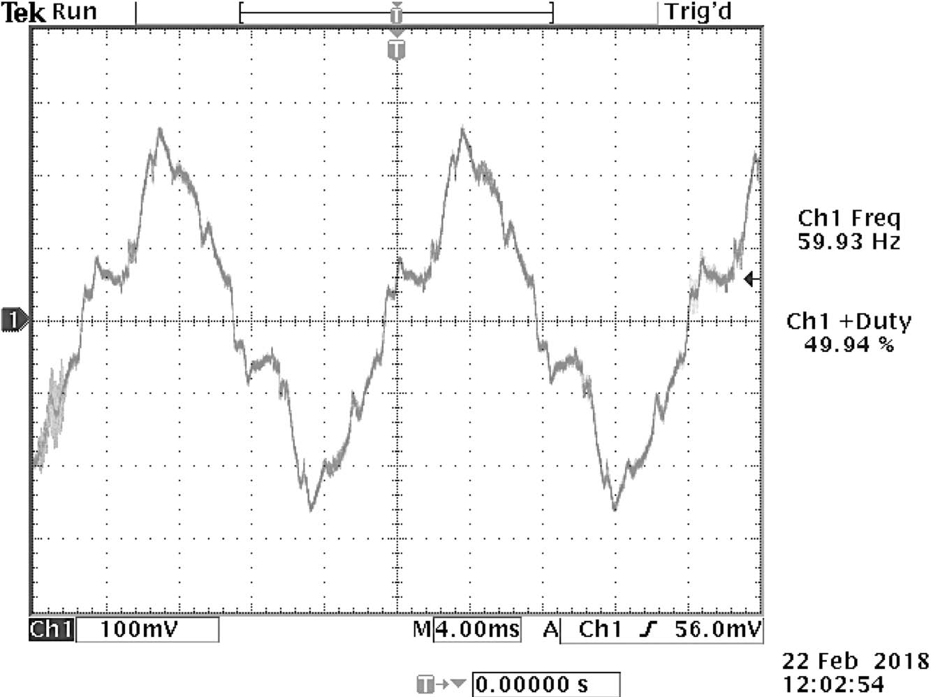
You may be asking, “What’s a harmonic?” A harmonic is an electrical signal that can be impressed on the ac line voltage or current that is some multiple of the base line frequency. We call the base frequency (60 Hz, for example) the fundamental, or first harmonic. Without harmonic distortion, this is the only signal present. Harmonic distortion introduces higher order harmonics: the second harmonic is 120 Hz, the third 180 Hz, and so forth. An example of ac line voltage containing multiple harmonics is shown in Figure 2c.
Non-linear, single-phase loads usually generate harmonics starting with the third, but only if the current has the same waveform for both the positive and negative voltages. Three-phase loads, such as a three-phase charger, generate harmonics starting with the fifth.
What’s wrong with harmonics? They don’t do any work in the battery charger or any other useful equipment (except for incandescent lighting or resistive heating). Instead they cause extra heating in the load, in the wiring to the load, in the distribution transformers, and all the way back to the generating station. Harmonic currents even force the utility to oversize the overhead distribution cables.
For any non-linear equipment, such as a battery charger, the input current may have harmonic distortion. The current distortion causes some fluctuation in the sinusoidal voltage that powers the charger; thus current harmonic distortion is translated to voltage harmonic distortion, which is then spread to other equipment in the facility. If the ac supply has a low impedance, such as that supplied by a standard distribution transformer, the voltage harmonic distortion that results is usually very low. Low harmonic voltage distortion is important to prevent excess heating in other loads connected to the facility’s ac supply.
Power Factor in Linear Loads
2.4.5.1
We mentioned power factor in the description of various ac to dc conversion methods back in SECTION 2.1.3. You may be familiar with power factor correction, where a facility will install a capacitor bank to raise the power factor presented to the utility source. This is a good way to compensate for inductive loads, such as large ac motors or ballasted (e.g. fluorescent) lighting.
If the current in a load is linear, and exactly follows the voltage, the power factor is 1.0. This is the most desirable situation. A lot of loads, however, such as ac motors, are inductive. This means that the current has the same shape as the voltage but lags the voltage by some phase angle. Mathematically, we define power factor for this type of load as the cosine of the phase angle between the voltage and the current.
Examine the waveforms in Figure 2d. This is the relationship you might expect to see in a fractional horsepower motor. The applied voltage (trace A-A) is 120 Vac (rms), and the motor current (trace B-B) is about 14 Aac (rms). Note, though, that the peak value of the current occurs later than the peak value of the voltage. We say that the current lags the voltage, which is what happens if the load is inductive. AC motors are inductive, especially if lightly loaded.
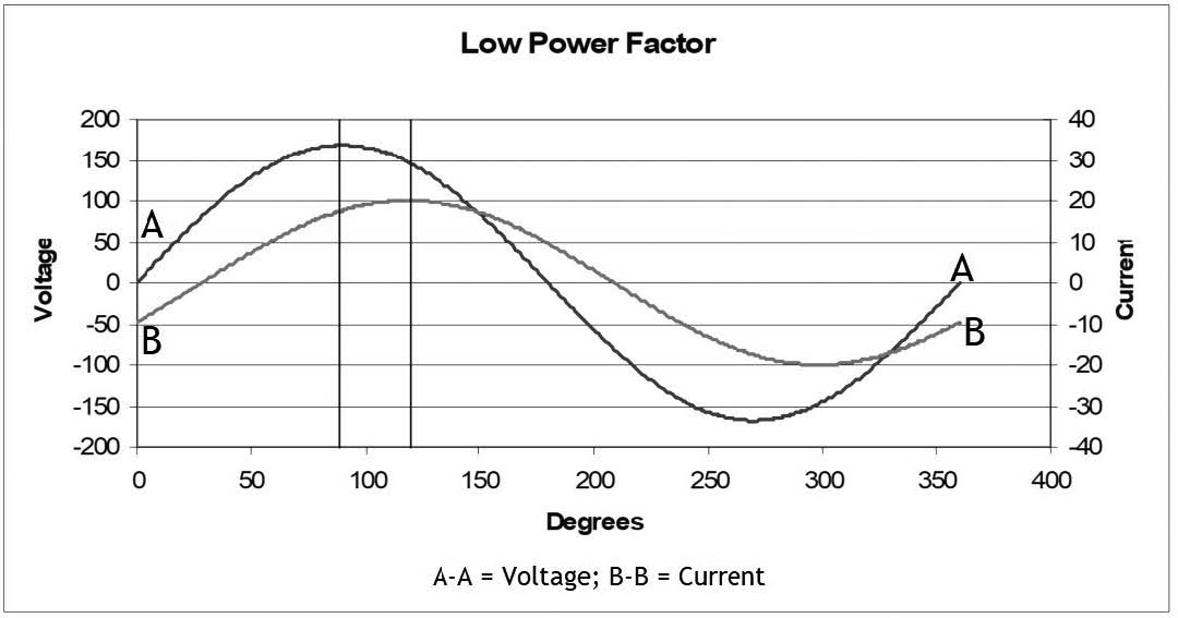
If you multiply the voltage by the current, you get 120 × 14 = 1680 VA (VA stands for volt-amperes). This isn’t all real power, though. The real power is lower, reduced by the power factor. The motor produces real power only when the instantaneous voltage and current are positive, or when they’re both negative. When one is positive and the other negative, it actually subtracts from the work done by the motor. By the way, power factor defined this way is also known as displacement power factor.
Vertical lines are drawn through the peaks of the voltage and current waveforms above. We can measure the time or phase difference between the peaks, in degrees. In the example above, it’s about 30 degrees. The power factor, then, for the motor in this picture is the cosine of 30°, or 0.866. So the real power, with rounded off values, is:
120 Vac × 14 Aac × 0.87 = 1,462 watts
I hedged a little bit when I called this example a “fractional horsepower” motor. At 1,462 watts, it’s a little over one horsepower (746 watts). To factor in average motor efficiency, you can use an approximate value of 1,000 watts per horsepower. You see that with an inductive load, we can calculate power factor by measuring the phase angle between the voltage and current. But utilities don’t do it that way. They say:
![]()
where PF is power factor, watts are the real power in the load, and VA is the product of the voltage and the current in the load*. The VA product, or volt-amperes, is never less than the power in watts, so that you cannot have a power factor greater than 1.0. A power factor of 1.0 is ideal, since the entire current contributes to powering the load.
Power Factor in Non-Linear Loads
2.4.5.2
When you calculate power factor as the ratio of watts to VA, you find that non-linear loads also have a low power factor, even if there is no phase angle between the voltage and current, during the periods when current is flowing. Consider a simple power supply, with a simple diode rectifier, and a large filter capacitor connected to the output of the rectifier. The diodes conduct current only when the applied ac voltage is higher than the dc output voltage of the power supply, but there isn’t a lag between the voltage and the current. Yet the power supply has a low power factor. Why? The answer is tied up in that definition for power factor, W ÷ VA.
The result is those pesky harmonics. When the current flows through the diodes for only part of a cycle, lots of harmonics are generated in the input current. But remember that harmonics don’t do any work; they just add to the VA measurement at the input to the power supply. So, the power factor looks low – actually is low – because of the non-linearity of the load. This is the way a phase-controlled battery charger behaves, and why the power factor for a charger is less than 1.0, especially at light load. At very light loads, you might not care about the power factor. For a substation application, where the float current is near zero, the power consumed by the charger is low – just enough to cover the charger’s fixed losses, such as power for the control circuits and the exciting current for the main transformer. The power factor in this condition will be low. The power factor increases as the dc output current increases, until the charger reaches its maximum power factor at full load. This usually ranges from about 0.8 to 0.9.
Incidentally, while the capacitor bank mentioned a few paragraphs back can compensate for an inductive power factor from linear loads, it does nothing for the low power factor caused by a non-linear load.
WHAT ALTERNATE AC POWER SOURCES CAN A BATTERY CHARGER USE?
2.4.6
Generators
2.4.6.1
Sites are sometimes equipped with auxiliary diesel generators, either to extend the backup time in power emergencies, or to provide power for a “cold start” for a remote or isolated power generator. Most battery chargers will operate fine with a generator power source, but the generator must be able to provide the necessary inrush current (see SECTION 2.4.3) when the charger is energized.
Generators are generally sized with some excess capacity in applications where ac motors or transformer-operated equipment are involved. For a full discussion of gener-ator sizing, see Can I run a charger from an auxiliary generator? in CHAPTER 7, Applications.
Multiple Grid Sources
2.4.6.2
Site planners sometimes seek a level of redundancy by having a second ac power source available for critical equipment. Of course, the battery charger is critical, right?
The ac power input for a charger can be switched between two (or more, but it gets complicated) ac sources, using suitably rated contactors. There will be a short interruption of power to the charger, since the switching contactors need to be in a break-before-make configuration. Because of the interruption, the charger will also trigger the soft start feature, so the interruption of dc output current may be several seconds. Keeping the battery connected to the dc bus is tactically important in this kind of installation.
Can a charger be powered by a UPS?
Well. The main question here isn’t “Will it work?,” but “Why?”