Temperature Compensation
Part of Chapter Temperature Effects on your DC system
WHAT TEMPERATURE COMPENSATION OPTIONS ARE AVAILABLE?
5.3.1
HindlePower’s AT Product Line (AT10.1, AT30 & ATevo Battery Chargers)
5.3.1.1
All AT type battery chargers use an external temperature probe, mounted on or near the battery, for temperature compensation. The same probe works with either lead-acid or nickel-cadmium batteries. When you order the option, you specify the length of the cable linking the temperature probe with the charger. Cables are available in 25, 50, 100, and 200 ft lengths (7.5, 15, 30, and 60 m).
HindlePower’s Original AT10 Battery Charger
5.3.1.2
Temperature compensation probes are not compatible between the older AT10 charger and the newer AT10.1 and ATevo models. When you order temperature compensation for the older AT10, you have to specify the model number, dc output voltage and battery type. A 25-ft cable is supplied as standard, but longer cables are available.
HindlePower’s SCR/SCRF Battery Chargers
5.3.1.3
SCR type chargers are normally supplied with an internal temperature probe (mounted in the charger enclosure) for sensing the ambient temperature in the space where the charger is installed. Please specify the dc output voltage and the battery type to be monitored.
HindlePower’s SCR/SCRF Battery Chargers with External Probe
5.3.1.4
An external temperature probe is available but requires additional components to be installed in the charger. Various cable lengths are available. Order according to battery type, charger output voltage, and cable length required. You must also order the High DC Voltage Shutdown option.
HOW CAN I MOUNT A TEMPERATURE PROBE RELIABLY?
5.3.2
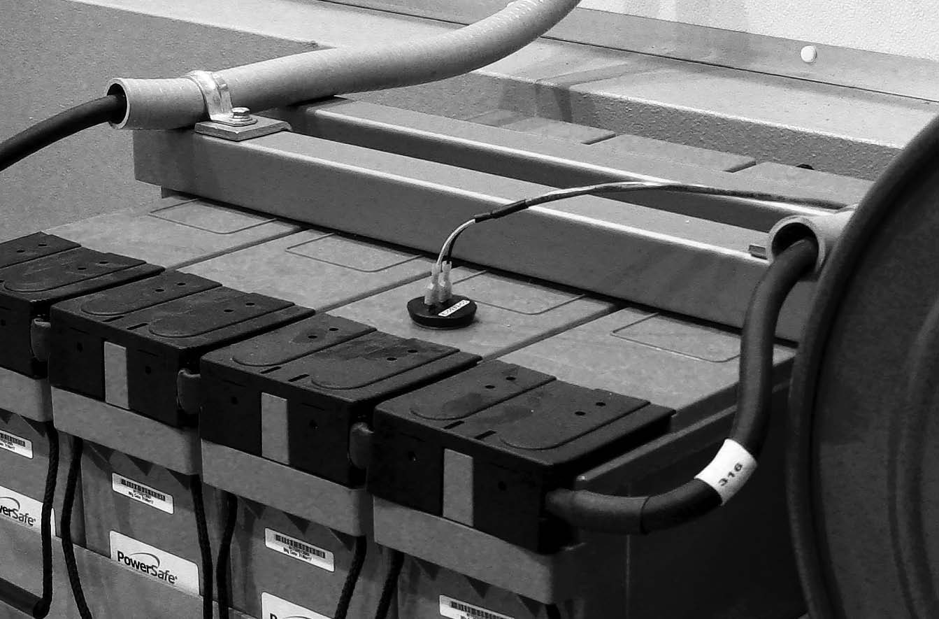
The temperature probe (see Figure 5a) is designed to mount “on or near the battery." But charger instruction manuals caution against mounting on plastic battery jars. This may cause some confusion. Reprinted in the boxout is an Application Note that we hope will clear up the confusion:
APPLICATION NOTE
When the AT series temperature probe was first designed, we were advised that the mounting adhesive might not be compatible with some plastic materials, including some used in manufacturing battery jars. To avoid problems, we advised staying away from all plastics as a mounting surface. We recently researched the adhesive again and can provide some additional guidance.
The mounting tape used for the temperature probe is a 1 mm (0.045”) thick neoprene foam, coated on both sides with an acrylic adhesive. The adhesive is compatible with a wide range of materials, including many plastics. It also maintains strength at elevated temperatures (up to 100 °C, although we hope your battery never gets that hot!). The neoprene foam conforms to irregular surfaces, allowing the probe to be mounted on rough or coarsely painted surfaces. The probe is electrically insulated, with at least 500 V isolation.
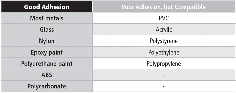
The adhesive is optimized for high surface energy materials (most metals, for example). Thus, bare wood and galvanized steel are still no-nos, although untreated zinc is all right. The adhesive is compatible with many polymers used in battery manufacturing. However, some polymers have very low surface energy, and reliable adhesion may be difficult to achieve. Those are the materials in the “Poor Adhesion” column in the table below. The materials in the “Good” column should provide good adhesion. Most painted surfaces are OK, but you need to know that the paint will stick to the surface like, well, paint.
We still recommend an intercell connector as the best place for mounting the probe. In a battery room with little air movement, the connector will be closer to the actual battery internal temperature than the outside of a battery jar.
Table 5a contains a list of compatible materials:
UNDER THE HOOD: HOW DOES TEMPERATURE COMPENSATION WORK?
5.3.3
What is temperature compensation? If you’ve read SECTION 5.1, How Does Temperature Affect Stationary Batteries?, you know that temperature changes can affect charging requirements. Temperature compensation is a feature of a battery charger that automatically adjusts the dc output voltage of a charger to provide just the voltage the battery needs at any temperature – that is, the voltage that will maintain the charge (float voltage). The goal is to keep the float current constant.

Why do we need to keep the float current constant? Stationary batteries are typically float charged for very long periods of time. We normally choose the float charge current so that it’s just enough to overcome the self-discharge rate of the battery. Any less, and the battery slowly self-discharges, and doesn’t have the capacity needed when it’s called upon to do its job (such as operating circuit breakers in a power emergency). Any more, and the excess current (excess ampere hours over time) causes electrolyte loss, grid corrosion, and other nasty things. The electrolyte loss is due primarily to electrolysis, which breaks up the electrolyte into hydrogen and oxygen. The hydrogen is explosive (Hindenburg syndrome), especially if it ends up in a confined space. The oxygen is generated at the positive plates, where it can cause corrosion, reducing the life of the battery. In sealed lead-acid (VRLA) batteries, the hydrogen and oxygen are normally recombined internally back into water, replacing the electrolyte that would normally be lost during extended charging.
Many years ago, battery manufacturers empirically determined the on-charge temperature coefficients of secondary batteries. The coefficients are functions of battery chemistry, and not physical characteristics such as flooded vs. “sealed” construction, or differences in grid alloys. Therefore, you won’t find any differences between, for example, antimony or calcium or selenium alloys for lead-acid, or between sealed and flooded NiCd batteries. With modern graphical tools, manufacturers can provide precise mathematical expressions for determining the correct float voltage at any temperature.
There isn’t a lot of consistency in the published values for temperature coefficients, for a variety of reasons. They may be determined at different float voltages, since the change in mV per cell is naturally a function of the float voltage. Some of the original measurements for lead-acid were done at a charge voltage of 2.4 VPC, since that was considered the threshold of gas evolution, and resulted in a temperature coefficient of -3.33 mV per cell per degree F. For example, in a 60-cell lead acid battery, the on-charge voltage would decrease by about 0.2V for each °F increase in temperature (while keeping the float current constant).
The output voltage of a battery charger is normally “flat.” That is, it doesn’t vary with temperature, pressure, relative humidity, or the phase of the moon. This would be fine in a perfect world, where your battery would be in a temperature-controlled room, with an air conditioner that was never down for maintenance. But let’s face it: That’s a pretty tall order.
In SECTION 5.1.5 on the temperature effects on batteries during charging, we learned that if you keep the float voltage constant, float current increases as the temperature goes up. That increase in float current, over the long haul, results in excess ampere hours of charge, causing electrolyte loss and grid corrosion, shortening battery life. If you have a VRLA battery, it will be tolerant of higher float current over a limited temperature range (about 15 °C to 30 °C); if you have a flooded battery, you can always add water to replenish lost electrolyte. But you’re still stuck with the grid corrosion, and if there’s a lot of gassing, there will be an excessive amount of active material knocked off the grids. Remember, that’s why there’s extra space at the bottom of the battery. Why take a chance?
There’s another factor with VRLA batteries. If you can guarantee that the battery will never be in a room above 30 °C (86 °F), you will be OK. But if your VRLA battery is mated to a non-compensated charger in a hot environment, you risk thermal runaway, wherein the increased float current causes internal heating, which raises the temperature, increasing the float current, etc., until you literally have a meltdown.
If you don’t use temperature compensation, and you keep your charger set to the float voltage specified for 20 °C, the float current doubles for each 10 °C increase in temperature. This results in increased electrolysis (loss of electrolyte) and requires more frequent addition of water. This is OK if you have a flooded cell type, but what if you have a VRLA, and you can’t add water? A VRLA will actually recombine the hydrogen and oxygen within a limited temperature range, as long as the gas evolution rate is within the design capability of the cell. If the gassing rate is too high, the cell vents the gas, and that means water loss: the cell begins to dry out, losing capacity.
On the cold side, the charging voltage should be increased if the battery is exposed to temperatures below about 15 °C (59 °F) for an extended period, to avoid undercharging. Undercharging sacrifices capacity, at the least, and undercharging for extended periods causes irreversible damage to the negative plates of a lead-acid battery.
Manufacturers sometimes specify the on-charge temperature coefficient for a battery, but there isn’t a lot of consistency. Based on history and research, HindlePower settled on a temperature compensation coefficient of -3 mV/Cell/°F for lead-acid (at about 2.2 VPC), and -2.7 mV/Cell/°F for NiCd (at about 1.42 VPC).
The slope (in percent) of the on-charge voltage should be the same at other float voltages. We translated the coefficients to values useful for electronic circuit design: -2.5 mV/V/°C for lead-acid, and -1.9 mV/V/°C for NiCd. By using mV/V (essentially the same as a percentage), the slope becomes independent of actual float or equalize voltages. So the factor of -2.5 gives us -3.33 mV/cell/°F at a standard voltage of 2.40 VPC, but at 2.25 VPC the slope is 3.125 mV/cell/°F.
The original design for the temperature compensation probe in the SCR/SCRF products used a thermistor network, in order to make the probe characteristics consistent in manufacturing. Installing the probe in the charger alters the feedback control circuit to achieve the proper voltage/temperature response. This is also the method used in early models of the AT product line. There is a downside to this method: Battery voltage is applied to the thermistor probe, and if the probe is mounted remotely (such as on the battery), damage to the probe wiring could cause catastrophic failure of the wiring and potential loss of charger voltage control.
The current AT design uses an arithmetic algorithm to calculate the required float voltage, but still uses a thermistor probe. However, accidental damage to the probe wiring has been fail-safed. In the event that a temperature probe would be damaged or the connection to the probe would be lost, the charger would revert to linear voltage control and display an error warning the user of probe failure.
In the full AT series charger line, the front panel voltmeter always displays the recommended float voltage, regardless of battery temperature. The actual output voltage of the charger will be different, and is a function of the current temperature at the probe.
In the SCR/SCRF charger, the front panel voltmeter displays the actual charger output voltage, which is adjusted according to the temperature at the probe. The reference temperature for temperature compensation is 25 °C. If the manufacturer specifies your battery’s float voltage at 20 °C, you need to adjust the charger output voltage for the difference. The best method is to disconnect the probe temporarily (reconnect the feedback resistor R2 into the circuit) and set the float voltage. Then reconnect the temperature probe. Alternatively, you can adjust the output voltage according to the graph shown in the charger instruction manual, but this isn’t as accurate.