Filters: How Do They Reduce Ripple?
Part of Chapter Ripple and Filtering
WHAT LEVELS OF FILTERING DO MANUFACTURERS OFFER?
3.4.1
Manufacturers handle filtering requirements differently, but most offer two levels of filtering: standard filtering and battery eliminator filtering. Both are adequate to reduce the ripple voltage at the battery to safe levels. Battery eliminator filtering offers additional filtering to ensure that connected equipment operates reliably even if the battery is disconnected for maintenance.
IS IT SAFE TO USE AN UNFILTERED CHARGER?
3.4.2

We can’t emphasize this enough: never buy an unfiltered charger. If you do, never disconnect the battery. If you do, never energize the charger.
Why? The output voltage of an unfiltered charger can have peak ripple voltages at least 50% higher than the nominal dc output voltage. Those peaks can damage sensitive equipment connected to the dc bus. Imagine plugging your desk lamp into a 240 Vac outlet. You’d have a lot of light for a little while. Maybe.
As we have seen, ripple, a small but regular variation in the dc output voltage and current of a charger, is an unavoidable consequence of converting ac power to dc power. Large amounts of ripple can affect battery life and pose a risk of equipment damage. Reducing the magnitude of ripple voltage and/or current is the job of a dc filter.
Why do you call it a dc filter, if ripple is ac?
True, we’re filtering out an ac ripple signal. Because it’s on the dc side of the rectifier, though, and the output of the filter is almost pure dc, we call it a dc filter.
BASICS: A LOOK AT RIPPLE
3.4.3
Take another look at the current waveform in Figure 3i. You can see that the current contains a lot of ripple; that is, there’s still a lot of ac in the output current, as well as the steady dc value of about 50 A. What you can’t see in that figure is the ripple voltage on the output dc bus, because we don’t yet know anything about the load: is it resistive, or is there a battery connected?
If you have ripple current, you’re going to have ripple voltage. If you have ripple voltage, you’re going to have ripple current. How much of each depends on the type of rectifier, the actual output current, the nature of the load, and... oh, yeah, whether we have a dc filter in the circuit.
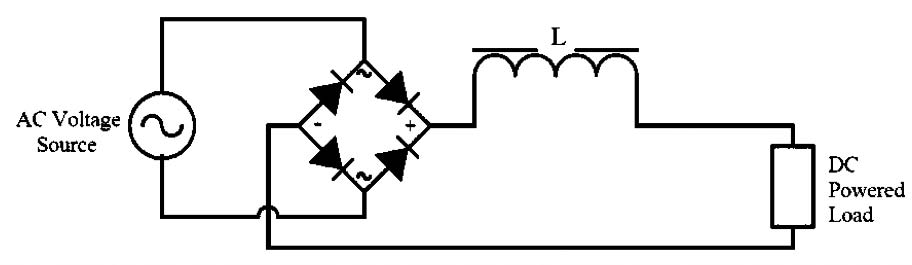
MAIN INDUCTOR: A GOOD START; SMOOTHS OUT THE CURRENT
3.4.4
As we saw in the section on ripple, a simple full-wave rectifier (with a resistive load) can have as much as 48% ripple on the output voltage. In a resistive load, that would be 48% ripple current. But as you saw in Figure 3i, adding the main inductor, as pictured in Figure 3j below, reduced the ripple current to only (roughly) 7 Arms. The way the math works, this amounts to only about 1% ripple, a vast improvement over 48%.
You may be asking yourself (I hope you are) how 1% ripple could damage equipment. The answer is that this is a snapshot at one operating point, which is the full load for this charger. At very light loads, the inductor becomes less effective at reducing the peak output voltages.
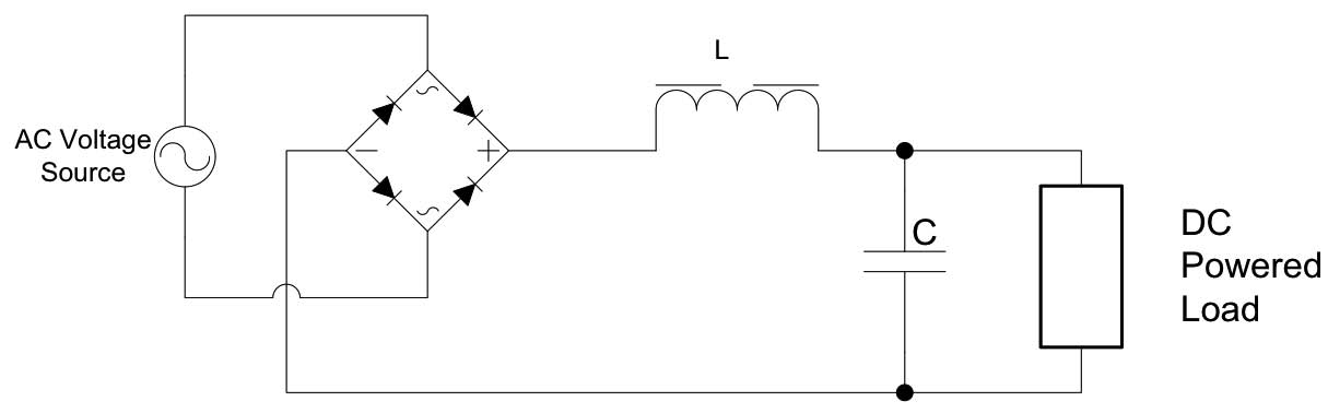
ENTER THE CAPACITOR: SMOOTHS OUT THE VOLTAGE
3.4.5
An inductor isn’t the only component with desirable ac characteristics. It does its work by impeding any tendency of the output current to change with changing voltage (hence, ac impedance). What we would like to have is an element that resists changes to voltage as the current changes. Wait, wait... we do. A capacitor has a very useful characteristic: We can apply to it a varying current, in this case the 7 A ripple current, and it will have relatively small changes in the ac voltage on its terminals – much smaller than a resistor with the same current.

So, if we put an inductor in series with the output current, it will tend to smooth out the current. If we put a capacitor in parallel with the load (resistor or battery; it doesn’t matter), it will tend to smooth out the voltage on the load.
Now we can draw the original full-wave rectifier, with a filter added that includes a single inductor (L) and a single capacitor (C), pictured in Figure 3k.
Let’s now look at some oscilloscope snapshots from a typical 130 volt, 75 ampere charger with an SCR rectifier that includes a filter consisting of a single inductor and single capacitor. These snapshots will help us see how these filter components smooth out the ripple in both the voltage and current delivered by the charger.
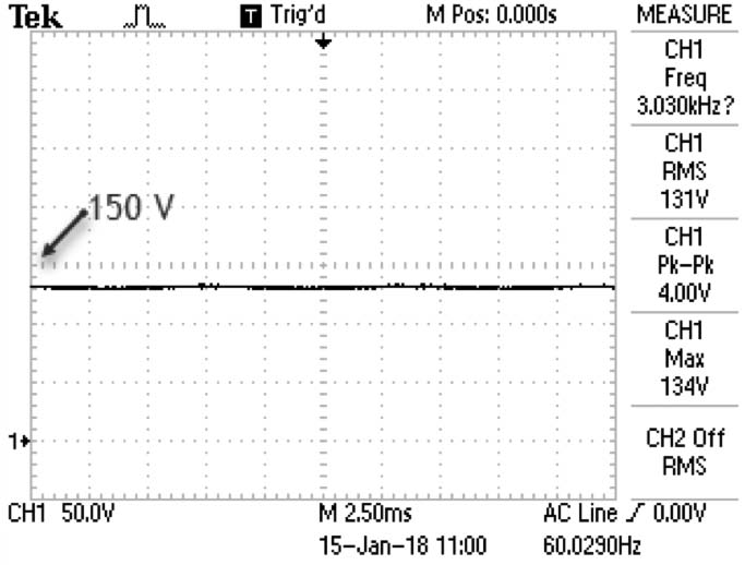
The following oscilloscope snapshot (Figure 3l) is the voltage before the inductor ‘L’. This is the voltage, unfiltered, coming straight from the rectifier. The voltage clearly has strong ac characteristics and significant ripple.
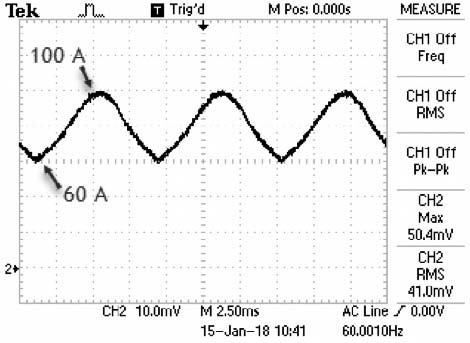
The current flowing through the inductor appears in the waveform shown in Figure 3m. Note that this current is measured with a clamp-on current probe which explains why the vertical scale is in millivolts (mV) and not amperes. The scale translation is 1 mV to 2 amperes such that each major vertical grid equates to 20 amperes. While the current waveform clearly still exhibits ac ripple, as mentioned earlier when discussing Figure 3i, the inductor greatly reduces the amplitude of the ripple.
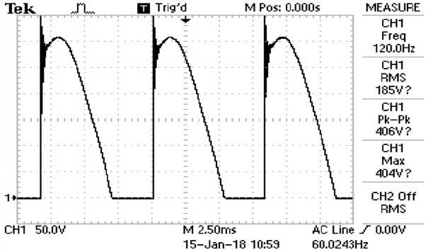
We can see that the presence of the capacitor in this filter smooths out the voltage delivered by the charger by comparing the last unfiltered voltage waveform (Figure 3l) with this next voltage waveform (Figure 3n). The waveform in Figure 3n is the voltage from the same charger across the filter capacitor (C) just after the inductor (L). The voltage now appears to be almost entirely dc, and the ripple voltage will typically be below 100mV when connected to a battery if the correct inductor and capacitor are selected.
While this filter, consisting of a single inductor and single capacitor as in Figure 3k, will work fine, we usually include a second inductor between the capacitor C and the load, forming a three-element filter. This improves the filtering performance when a battery is connected. A battery eliminator filter includes yet another capacitor between that second inductor and the connected load (you guessed it: a four-element filter); this ensures that you have the same filtering level in situations where there is no battery connected in the circuit.