How Does Current Limit Work With Various Chargers?
Part of Chapter Charger Output Current Limit
SCR/SCRF PRODUCTS
4.4.1
Current limit is specified to be adjustable from 80% to 120% of rated output. In practice, the adjustment range is wider; you can probably get a range of 50% to 125% or more. But please note that everything in the charger is designed for a maximum of 120%; trying to get more output current can overstress internal components.
Another important part of the current limit specification is the transient response. The question is, what happens when there’s a sudden load demand, and the output current tries to shoot past the current limit setting? You could have this situation, for example, while trying to start a dc motor, which has a large inrush current. In HindlePower’s SCR/SCRF charger, there is a short delay, about 100 ms, in the operation of the current limit circuit. During this time, the charger typically can deliver up to four times its rated output current. Because of this response, the charger contributes some of the motor inrush current; the rest is supplied by the battery. Obviously, if ac power fails, the battery must supply the entire inrush current.
Figure 4a shows the response you might expect to see during motor starting. This graph shows the result of a test at a gas turbine site. A 130 Vdc system includes a lube oil pump, rated at 60 A full load, and a three-phase SCRF charger rated at 75 A full load. This graph is for one combination of charger, battery, motor, and site arrangement, which includes how the dc wiring is run. Your results may differ.
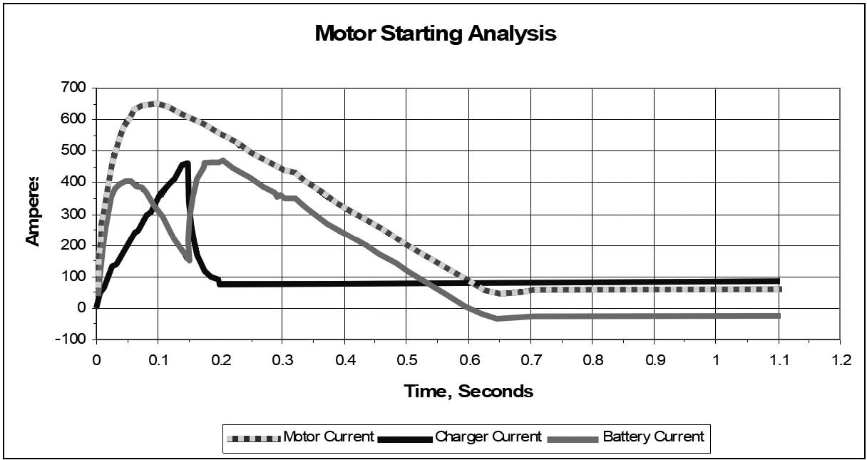
Note that the motor inrush current (dashed trace) reaches 640 A, about ten times the motor’s rated full load current. This is typical. The inrush current is shared by the battery (medium gray trace) and charger (black trace). As the charger starts to limit the output current (at about 150 ms), the battery picks up more of the load, until it supplies the entire load current, less the 83 A provided by the charger (current limit was set to 82.5 A, which is 110% of the charger rating). When the motor is up to run-speed and its current drops to about 60 A, the charger supplies all the motor current, and also starts to recharge the battery.
At this site, an inrush-limiting motor starter wasn’t used. A starter reduces the peak inrush current at the expense of startup time; instead of reaching full speed in less than a second, the motor takes several seconds to start, and starting torque is reduced. Incidentally, the charger at this site is equipped with a “motor starting” option, which replaces the standard dc fuse with a slightly slower rating, allowing it to survive the 150 ms delay in current limiting action.
Try to avoid a bus fault (a “bolted” short circuit on the dc bus). In such event, a charger would try to produce the same peak output current into the short circuit. After the delay, the charger would output its current limit value. If a charger is filtered, however, the filter capacitors would discharge quickly into the short circuit, and there would be a risk of clearing the dc output fuse. The risk would be especially high for a battery eliminator filter. If this would happen, the charger would be out of service until the fuse would be replaced.
AT PRODUCTS (AT10.1, AT30, & ATevo)
4.4.2
The current limit is specified to be adjustable from 50% to 110% of the rated output. These limits are fixed by the control program, so you can’t exceed them the way you might in the SCR/SCRF product line. Also, the response time is faster, so that peak output current is reduced.
The limited output current for HindlePower’s AT charger means that a sudden load demand, such as a motor starting, requires the battery to pick up the entire incremental load. The AT charger has another feature, called a current crowbar, that protects the charger in case of a fault on the dc bus. If a fault causes an exceptionally high output current, the charger shuts down instantaneously, and restarts using its built-in soft start, or walk-in. If the current crowbar should be activated, for example, by starting a dc motor, there would be at least a four second delay before the charger would be able to contribute current to the load again.
With a dc bus fault, the AT provides its current limit value into the short circuit. The AT is designed to survive a bus fault without clearing any output breakers or fuses, so that human intervention isn’t needed once the fault is cleared.
Why are there differences in the transient responses between the SCR/SCRF and AT?
4.4.2.1
The SCR/SCRF control circuit is an analog design. The response time is a trade-off between accuracy and stability. The delay was not a design objective, but it does give a little extra oomph for motor starting.
The control circuit in the AT charger is a digital design, so the current limit is controlled by software and tuned for fast response. It includes the current crowbar feature mentioned earlier that provides extra protection against damage due to a dc bus fault.
UTILITY CHARGERS
4.4.3
The UMC (Universal Maintenance Charger) and RMC (Railroad Maintenance Charger) are based on SCR/SCRF technology and have the characteristics described above. The RMC, however, adds a short-circuit detector feature because of the clamp-type battery connectors. If the output leads are accidentally shorted, the charger shuts down at once; the current limit circuit is out of the picture as long as the output is shorted.
SC CHARGER
4.4.4
The SC (Single Cell) charger is based on an SMPS and is limited to 100% of its rated output (10 Adc). You can select lower output current ratings of 3 Adc or 6 Adc, but these settings are resistively (not electronically) controlled, and the current limit may be “softer.”