Under The Hood: Source of Ripple
Part of Chapter Ripple and Filtering
BEFORE YOU GET started here, you’ll find the material in CHAPTER 2 on battery charger technology helpful.
UNAVOIDABLE BYPRODUCT OF CHANGING AC POWER TO DC POWER.
3.2.1
Ever since Tesla and Westinghouse showed us the way to make ac power transmission practical, we’ve spent a lot of time and effort developing better ways to change ac power back into dc power.* We need dc, of course, to charge batteries, and also to power critical equipment that must operate in the absence of the primary ac power source. Following is an overview of the methods we have of converting ac power to dc.
What are some early ways of changing ac to dc?
3.2.1.1
In the beginning, we used rotating machines. Can you say maintenance? Size? Weight? Noise? Ozone? As soon as the mercury arc rectifier became commercially viable (in the 1920s), industries moved quickly to adopt static converters (that is, no moving parts), although small M-G (motor-generator) sets persisted until the 1960s.
Development of the ignitron, thyratron, and other controlled rectifiers enabled phase-controlled rectification or conversion, which provides a much easier path to controlling the output voltage and current of a converter. With the exception of small thyratrons, however, these devices had a large drawback: a large pool of mercury, essential to its operation.
Enter the mag amp (magnetic amplifier), an older technology dusted off and used extensively in WW2. In the 1960s, magnetic amplifier converters were developed that used transistors and semiconductor diodes to replace vacuum tubes and gas-filled or mercury rectifiers. These solid state converters are very rugged, and have low maintenance requirements, but require complex and expensive magnetic components.
So chargers mostly use SCR now? What’s that?
3.2.1.2
In the late 1950s, GE developed and commercialized the SCR (silicon controlled rectifier).*
Like a diode, it conducts current in only one direction, so it’s ideal for converting ac power to dc. But it’s like a diode on steroids: We can force it to conduct for a full cycle, or for any part of the cycle we wish.
A cycle?
3.2.1.2.1
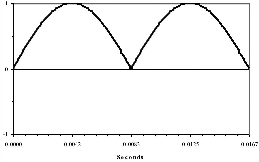
Right. At this point, we can’t avoid a graphical explanation. You heard E, in the play earlier, explain that ac voltage changes from positive to negative and back, 60 times a second. If you could see ac voltage (and your eyes were fast enough), it would look like the waveform in Figure 3a.
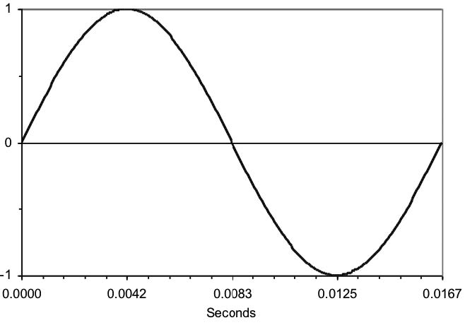
At the beginning of this picture of an ac waveform, the value of the voltage is zero. It rises to a maximum positive value, returns to zero, then goes to a peak negative value, and finally returns to zero. That is, it alternates; the positive and negative halves together make one full cycle. And it does all this in 0.01667 seconds (or 16.67 milliseconds)! Then it does it again.* And again. *
This is a sine wave. There are other useful waveforms, such as square waves, but utilities like to generate sine waves because they require less energy than any other waveform to generate and waste less energy in transmission.
Now we need to change the ac voltage into a dc voltage. Since, by definition, dc voltage isn’t supposed to alternate, we’d expect it to be always positive, or always negative. We’ll play with positive. Here’s a picture of a rectifier circuit (see Figure 3b), consisting of one diode, connected between an ac voltage source and a piece of dc-powered equipment.
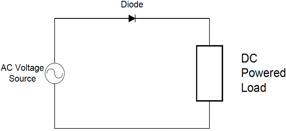
Ideally, we would like the voltage waveform we apply to the dc-powered load to be a smooth, non-varying straight line, just like we would get from a battery, unwavering for all time. Ain’t gonna happen. Since the diode only conducts in one direction (conventional current flows clockwise in Figure 3b), only the positive half of the ac voltage waveform gets passed to the load as seen in Figure 3c:
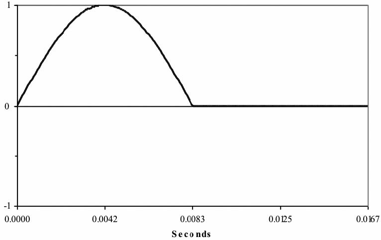
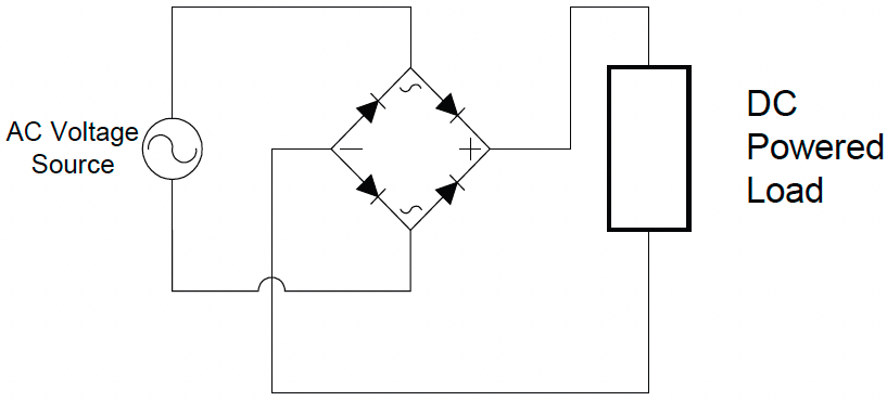
As you can see, the voltage applied to the load is always either zero or a positive value, and current will flow to the load only during one half of the cycle. So it’s a dc value, but it has a lot of ac left in it. There are rigorous mathematical methods to determine just how much and what kind of ac voltage is left, but we’re going to spare you. Instead, we’ll take the next step, in order to make the ac to dc conversion a little more efficient. Instead of a single diode, we’ll use a diode bridge, so that current flows during both halves of the ac voltage cycle (see Figure 3d). This is called a full-wave rectifier; the preceding circuit, you might have guessed, is a half-wave rectifier.
I see this new circuit uses four diodes. Can’t we do it with two diodes?
3.2.1.2.2
Actually, you could, but it makes the main transformer in the charger a little more complicated and expensive. Diodes, even with their heat sinks, cost less than the more expensive transformer. The downside is that each diode consumes a little energy, so this configuration generates a little more heat than the two-diode version.
Anyway, the advantage to a full-wave rectifier is that the negative half cycle, which was simply blocked in the half-wave rectifier, gets inverted, and becomes another positive half cycle when it’s delivered to the dc load. Figure 3e shows the dc output from a full-wave rectifier:
Now you can see that the voltage applied to the load is positive most of the time. Current flows into the dc load for the whole cycle, not just for half of it. It might not be readily apparent, but this voltage waveform has less ripple than the half-wave version. And, of course, it’s primarily dc voltage, which powers the load.
That’s a pretty messy waveform. How much dc voltage is actually in there?
3.2.1.2.3
Glad you asked. Since this rectified wave originates from a sine wave, it obeys some pretty consistent laws. The average dc value (that’s the part that powers the load) is 0.637 times the peak value of the voltage. So if we want to control the dc voltage applied to the load, all we have to do is control the peak value of the ac voltage, which normally comes from a distribution transformer, or a transformer in the rectifier. Easy, eh?
No.
We wish it were that simple. But dc equipment (including battery) voltage requirements aren’t always the same, the ac power line voltage isn’t always the same, and if you’re using a temperature-compensated charger, you know that the temperature varies, probably more than anything else. What we need is a way to control the average dc voltage output of the rectifier while everything around it is changing.
Before you take off on that, just how much ripple is there in that full-wave rectifier?
3.2.1.2.4

In the full-wave rectifier? About 48%. That means that if you have a 125 Vdc rectifier, the ac ripple you’re applying to the load is about 60 Vac. But remember a couple of things: we’ve been talking about a pure, relatively simple rectifier, connected to a resistive dc load – not a battery. Because a battery’s terminal voltage will “push back” against the rectifier, the waveform changes, and your ripple results may vary. Also, remember that it’s the peak value of the ripple voltage that may damage equipment.
Now, since you didn’t ask, I’ll tell you anyway. The lowest ripple frequency in the full- wave rectifier is 120 Hz, twice the frequency of the ac power line. But in the half-wave rectifier, it’s 60 Hz, the same frequency as the ac power. 60 Hz ripple is much harder to get rid of than 120 Hz ripple, another good reason to use a full-wave circuit, and stay away from half-wave rectifiers.
I’m curious now. How much ripple is in the half-wave rectifier?
3.2.1.2.5
It’s in the neighborhood of 121%. Sorry you asked? By the way, the ripple numbers here are the percentage of ac ripple voltage in the average dc voltage from the rectifier. That means that if you had a full-wave rectifier that gave you 1.0 Vdc (average) output, the ac ripple voltage would be 0.48 V. Notice that we give the ripple values as a percentage of the average dc value, not the peak value of the original ac waveform.
Isn’t there any kind of rectifier that produces less ripple, instead of more ripple?
3.2.1.2.6
Yes, and that’s one of the big advantages of three-phase power. (Remember Nicola Tesla? He developed the concept of three-phase power transmission that’s so widely used today. No, he didn’t develop an electric car.) Even the simplest three-phase rectifier has only one-third the ripple of a single-phase full-wave rectifier, and it gets better from there. But remember that these numbers are for resistive loads.
OK, now tell me how you’re going to control that output voltage.
3.2.1.2.7
Thought you’d never ask. We mentioned earlier that several technologies for ac to dc conversion were developed over the years, and each had a unique method of control. For rotating machinery (motor-generator, or MG sets), you could vary the excitation field on the generator. You could also vary the speed, but since the generator is driven by an ac motor, that’s harder to do. Mag amp and controlled ferroresonant circuits are easier to control; all you have to do is vary the control current in the winding(s) of one or more of the magnetic components. Each of these methods has its advantages. But we would like a method that doesn’t depend on complex transformer and reactor design.
Enter Phase Control
3.2.1.3
Do you remember that, a few paragraphs ago, a famous writer mentioned the SCR? To refresh your memory, an SCR is like a diode on steroids: We can ask it to conduct for a half cycle, or any portion of a half cycle, in a process called phase control.
First cycles... now you hit me with phase. Are these things related?
3.2.1.3.1
Couldn’t have said it better myself. Remember Figure 3a that pictured a single cycle of ac voltage, starting at zero volts, and ending up at zero volts? Now imagine that waveform broken up into 360 little bits (degrees, actually), with the start at zero degrees and the end at 360 degrees. You may be saying, “Oh, just like a circle.” Which is true, since a sine wave is mathematically related to a circle.
Now take just the first (positive) half of the sine wave. It runs from 0 to 180 degrees, and the peak voltage occurs at 90 degrees. You can think of each of these degrees as being a phase angle. Now consider that a regular diode, in a rectifier circuit, conducts current for the whole 180 degrees, the duration of the half cycle. If we could tell the diode to conduct for only half of the half cycle, well, we would have an SCR. When we command the SCR to start conducting current, we are turning it on. And if we could tell the SCR to conduct current for only half of the half cycle, through the magic of an SCR Gate Trigger Circuit, we would wind up with a voltage waveform sent to our dc load that looks like the bottom waveform in Figure 3f.
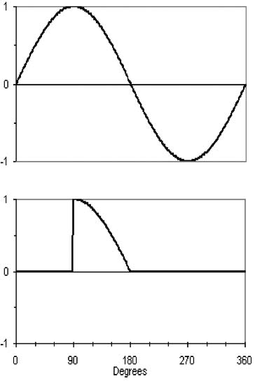
There are a couple of new features in this picture. Note that the phase angle, in degrees, is shown along the bottom, instead of seconds, although the time elapsed, in seconds, hasn’t changed. Also note that the original ac waveform, which is the voltage applied to the input of the rectifier, is shown at the top; the output of the rectifier is shown under it. The vertical axes show the values of the waveforms. In this case each voltage waveform has a peak value of 1 volt.
You can see that the voltage applied to the dc load is zero until the phase angle reaches 90 degrees. Then the SCR turns on, and the output of the rectifier then suddenly jumps to the peak value, which is the value of the ac input voltage at 90 degrees. If we have a resistive load, the current does the same thing. With a resistive load, the output voltage and output current have the same waveform, which is also the waveform of the incoming ac voltage.
But earlier you said that a battery isn’t like a resistive load. What happens in that case?
3.2.1.3.2
Good question. You might suspect from the previous picture that the ripple in the output of a controlled rectifier (that is, a circuit using one or more SCRs) is definitely going to be different from a half-wave or full-wave rectifier using standard diodes. However, if you connect the output of a controlled rectifier directly to a battery, the ripple might not be higher. Other components in the rectifier circuit can change the ripple values by modifying the output waveforms.
Before you start modifying waveforms, tell me how I can make the SCR conduct for the first 90 degrees instead of the second 90 degrees.
3.2.1.3.3
Uh, I can’t. It would be nice, of course, if we could make the SCR conduct for however long we wanted, anywhere within the cycle. But the way an SCR works is that it keeps conducting forever after we turn it on, as long as current is flowing through it. It turns off (stops conducting) when the current through it is reduced to nearly zero by other circuit components, or by the ac power source itself. If we wanted to turn it on at zero degrees, and then have it turn off at, say, 90 degrees, we would need some method of forcing the current to go to zero just when it’s at its maximum value. We don’t do that with ac to dc converters.
A type of SCR called a Gate Turnoff (GTO) SCR could be made to conduct for the beginning of a half cycle (that is, the first quarter of the cycle), and then be turned off for the second quarter. They’re useful in inverters but are not normally used in ac to dc converters.
There are circuits that will do that (inverters, for example), but they’re more complex and more expensive, and unnecessary in a rectifier. You can see in the preceding figure that the voltage goes to zero at 180 degrees; with a resistive load, the current also stops at that point. At this point, the SCR turns off by itself. It gets some help by the fact that the ac voltage on the SCR goes negative in the next half cycle, guaranteeing that the SCR current comes to a screeching halt. We call this line commutation, where line refers to the ac line, and commutation is the process of turning off the SCR. So, basically, if we want to control the voltage or the current in a rectifier (for example, by increasing the current from zero to a higher value), we start turning on the SCR at the end of the half cycle and move the turn-on point (phase angle) toward the beginning to increase the voltage or current. The point where we turn on the SCR is called the firing angle.
I get that. I’m a commuter, too. But you only have a half wave there. Can you make a full-wave SCR circuit with phase control?
3.2.1.3.4
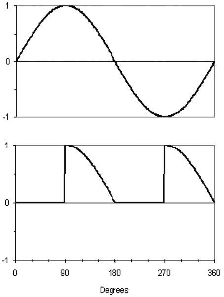
Now you’re really getting it. Using a bridge circuit consisting of just two SCRs and two diodes, we can get power for the dc load that looks like the bottom waveform shown in Figure 3g.
Note that we get a pulse of output voltage in each half cycle. As before, this waveform will have less ripple than the half-wave version for any firing angle of the SCRs, but the half-wave and full-wave circuits both have more ripple than a simple rectifier using only diodes (for the same average dc voltage). Once again, for a resistive load, the current waveform in the load would look just like the voltage waveform.
I’ll buy that. Now let’s see what happens when you connect the rectifier to a battery.
3.2.1.4
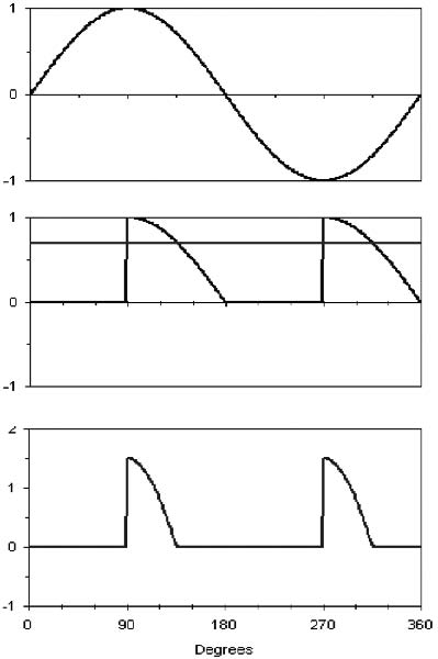
OK, you’ve been patient, waiting for this. Remember the picture of the waveform for a full-wave rectifier? Now consider this: if we connect a battery to the rectifier, the battery terminal voltage is going to push back against the output voltage of the rectifier. But since the battery voltage is constant, and the rectifier output isn’t, the rectifier voltage is going to be greater than the battery voltage only part of the time. Take a look at this three-part waveform (Figure 3h).
Wow! Now you’re really getting complicated.
3.2.1.4.1
Yes, there’s a lot more to chew on in this picture. Note the horizontal line cutting right through the rectifier output voltage pulses in the middle graph. That line is the dc voltage of the battery. Note that the rectifier output voltage pulses exceed the battery voltage only a small part of the time. Then, in the bottom graph, you see a waveform representing the current flowing from the rectifier into the battery. The current, as you see, flows only when the rectifier output pulse is larger than the battery voltage.
Why doesn’t the battery voltage change, and just follow the voltage of the rectifier?
3.2.1.4.2
That’s a good question. In this example, we’ve kept it simple by assuming that the battery is a perfect voltage source. In real life, the battery is a very good constant voltage source, but you will see the voltage change a tiny bit when the current flows from the rectifier. And that tiny change is the source of the ripple voltage that appears on the battery terminals.
OK. A couple of observations here. First, because the current pulse is so short, it looks like most of the voltage from the rectifier is wasted. Second, how do you know much current you’re actually getting?
3.2.1.4.3
You’re hired. You’ve just found the essential shortcomings of this simple rectifier circuit. Take the current magnitude: since there isn’t any extra impedance between the rectifier and the battery, you could get a lot, a lot, of current flowing. As you know, current limiting is an essential feature of a charger. The only limit to current flow here is the inherent resistances of the wiring, the transformer, and the battery, which are all deliberately kept very low (these are known as parasitic resistances). We could put in a separate current-limiting resistor, but if you want to talk about wasted power....
And you recognized the other limitation: The current flows for only a brief time in each half cycle. This leads to higher ripple and more power losses. Fortunately, there’s a single solution to both shortcomings, in the form of an inductor.
Enter the Inductor
3.2.1.5
An inductor is also known as a choke or coil. This is a magnetic part, separate from the main transformer in a charger. It acts as an ac impedance.
An ac impedance? I thought you were trying to limit the dc current.
3.2.1.5.1
Oh, we are. This isn’t magic, but it might seem that way. An inductor stores energy in a magnetic field, and we can use that feature to solve the aforementioned problems.
I thought you wanted to charge a battery, and now you’re playing around with storing energy?
3.2.1.5.2
Right. Here’s the way it works. We put the inductor between the rectifier and the battery. It has just two terminals – an input and an output. Whenever the rectifier voltage is larger than the battery voltage, the inductor takes the energy caused by that voltage difference and stores part of it in its magnetic field. Then, when the rectifier voltage decreases below the battery voltage, the inductor uses that stored energy to continue to deliver current to the battery. In this way, we force the current to flow for a longer period than shown in the previous waveforms. Larger inductors–that is, inductors with more inductance–are more effective at smoothing the current. Obviously, there’s a trade-off between inductor size and cost on one hand, and current smoothing on the other.
Is that all there is to it?
3.2.1.5.3
Well, “all there is” has a lot of benefits. First, we reduce the ripple current, and that reduces the ripple voltage on the battery. Second, we reduce the rms current in the SCRs, transformer, etc., which makes life easier for them. Third, we get to use most or all of the voltage from the rectifier, instead of just a small part. I believe that was one of your objections earlier.
It was. But now you’ve hit me with another zinger. What’s rms?
3.2.1.5.4
RMS (or rms) stands for root mean square, a mathematical description of dynamic waveforms. You don’t have to remember that. The only thing you have to know is that it refers to what we call the effective value of an ac voltage or current. It’s the measure of the heating value of ac power. We use it so we can equate dc and ac values. For example, a light bulb that takes 1 ampere at 120 V will consume 120 watts. If it’s dc, we measure average voltage and current; if it’s ac, we measure rms voltage and current. That 120 V, available at your standard wall outlet, is actually 120 Vrms.
So, rms voltage multiplied by rms current will give me rms power, right?
3.2.1.5.6
That depends on just how much output current we need, and how large the inductor is. We try to design the charger so that the inductor is “critical” at the extremes of operation. That is, at the lowest battery voltage we would expect to see on a normally discharged battery, and the highest ac input line voltage, all at full rated output current. Since I know you’re going to ask, I’ll tell you that a critical inductor is one that is sized to force each SCR to conduct for a full half cycle, and that a normally discharged battery is one that has been discharged to 87.5% of its “nominal” open-circuit voltage, measured while load current is still flowing. For example, a 60-cell lead acid battery, with a nominal open-circuit voltage of 120 V, would be discharged to 105 V. That number may be different for some battery types and in some applications.
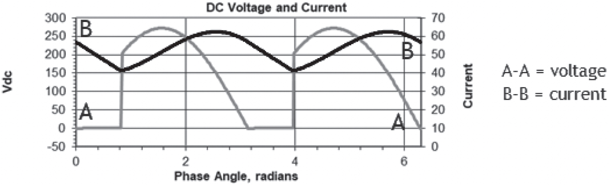
Finally, to answer your last question, here’s an example of what the output current waveform might look like with a critical inductor, forcing the current in each SCR to be continuous for the entire half cycle (see Figure 3i).
This is an example for a 130 Vdc charger. Notice that the current has a peak value of about 60 A, but a minimum (valley) value of 40 A, and never goes to zero; thus, it flows continuously, even though the voltage waveform is discontinuous. In this example, the SCRs are gated on at about 48 degrees. Don’t let the phase angle in radians throw you; that’s just an alternate to degrees (180 degrees is approximately 3.14, or pi, radians).
I think I understand this. With continuous current flow, the ripple will be lower.
3.2.1.5.7
Right on the mark. The ripple voltage on a 200 Ah battery for the conditions shown above would probably be less than 30 mV (millivolts).
But, but, but... the output current ranges from 40 A to 60 A. How can the ripple be so low?
3.2.1.5.8
Aha! That’s through the magic of the effective capacitance of the battery working in tandem with the main inductor. You’re right that the ripple current is high; notice I said that the ripple voltage was reduced at the battery terminals. And interestingly, the ripple current shown above is only about 7 Arms. To understand all that, continue reading to the section on filters.